Blog

Dumpster Dive Competition

This isn’t a terribly complicated circuit but more so using basic laws to maximize resources available and knowing which ones to use.

We had a “dumpster dive” competition last semester and my team won the racing/speed portion with our racer “The Unicorn”. More info for the event and setup can be found on my friends YT channel here. The circuit is simply AA batteries soldered in series driving directly to a DC motor. We tried to make a branch of LEDs which were lighting before the race but sadly disconnected right before. The CD rainbow mohawk was for added aerodynamic speed. The body is an old scanner, the chassis a printer mount, DC motors came from another printer, and the wheels from pizza boxes that were brought to the event and then hot glued for traction.

56219841_2574420202571467_2799729922875064320_o

Diffraction ID

Update! Second phase of project is complete. New housing set up and new mechanisms found to be implemented in the next phase. Still about two phases away from the final thing with a custom PCB but definitely making progress.

The housing has a slot for the coin cell 3V battery in order to easily show anyone interested. A bar magnet was placed inside which allows me to stick it anywhere on my clothes and without damaging them. It also just looks super cool to slide off and hand to someone, then “magically” snap it back on. The next phase after this will be making a custom PCB to minimize power loss and improve overall performance. Last phase will be putting in some mechanical touches to bring everything together. IMG_20200323_174143.jpg

This is a project I’ve wanted to get to for awhile, so excited to share what I got done. This post will be more process oriented until I get some other features and final product done.

IMG-806da40a74b655265a38fa34a71ac2c9-V

Basically it’s an acrylic plate that’s laser cut with my name, major, and important clubs (Engineers without Borders, Student Veteran Organization). The LED light from the top diffracts out of the etched letters in the acrylic to make the “floating” and glowing effects. Light also refracts out of the sides making a cool highlighting effect as well. Originally I was going to use an EL panel to just back-light some cut out letters from black backing, but I found out about a new makerspace on campus and jumped on it. For the overall design I’m trying to minimize it as much as possible so that when latched on your shirt no other components will be visible.

20190424_131105.jpg

I used Inkscape (versus paying for Adobe Illustrator) to get the files created and made in the correct format [2 hours]. Laser cut a few test pieces and extras [1 hour]. Cleaned up the dust with a dremel and polished the plate [30 minutes]. Then built the test panel pictured above [3 hours due to fighting myself about how to organize everything to keep as small as profile possible]. I still need to 3D print the enclosure for this basic one, and hopefully leave room for future features. Once I have that it’s just wiring the power source (a 3V coin cell battery), and adding magnets to the back for shirt attachment.

Future features I want to do are hopefully figuring out a way to attach a typical LED strip without having to deal with an adapter box, making a “breathing” light mode, a swath light mode, a light based on/off, and big moon goal is getting power to the board without a wire poking out or through anything.

The board was cut off and has resistor+LED pairs in parallel for stability reasons. In the picture below you can see the general wiring scheme. I typically will wind wire like this to allow efficient testing during building the base outline of the circuit before soldering things together. Once I actually start soldering I’ll keep it on there so I don’t have to make long solder lines, and easier to remove stuff in and out before I have a final product.

Captureasf.PNG20190426_230800.jpg

Modular Security

This semester I worked with Violeta Flores to develop a modular security system for our ECE outreach group at Colorado State University. This is one of many projects made to show various applications of mathematics, engineering concepts, and effective design for high school aged kids. For this project we placed it in a box (and did tests on doors) so that when the box is opened the device blares a whooping and whining alarm. While you can make more robust systems, this project was mainly geared towards introducing electrically based sensors to make those concepts more digestible for beginners.

Originally  we wanted to make it send a text or email log and alert, but in the limited time we were unable to implement it due to network security issues. What we were able to ensure the removal of any one sensor does not affect the security system, and the presence of other sensors do not impact another’s ability to perform. This corresponds to the “modular” nature of the device. The alarms were set differently so that you could tell which sensor reading was triggering the alarm.

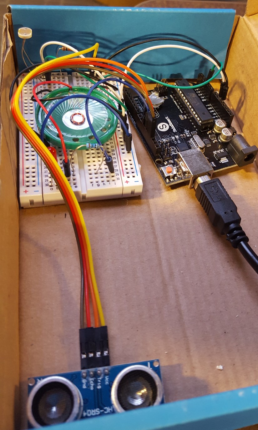
You can show these sensors, invite questions, and ask for suggestions on how to improve the circuits capabilities or resiliency to attacks with students. Exploring this can begin a journey into the deep wealth of possibilities in Electrical Engineering. This also starts a conversation about some of the modern problems we face with IoT, cyber warfare, and makes an emphasis on the many different design perspectives in ECE. One could spice up an event by placing a $5 bill and challenging students to retrieve it without setting off the alarm. The overall circuit (Fig 1) costs about $25 to make, though you could make it for ~$10 using simpler circuitry. Additionally the removal of any one sensor does not affect the security system, and the presence of other sensors do not impact another’s ability to perform.

I largely just had fun learning about all the different sensor types and how each sensor actually works in a more physical way rather than just the code, as typical for an arduino project. A majority of the time spent on this project was researching the different sensors and writing lesson plans to demonstrate the ones we ultimately choose to use. I look forward to expanding this project to more complicated examples, and specifically hope to make models of the US electrical grid to more personally explain its current security issues.

Fig 1: Overall circuit

20190415_192250.jpg

Sensors

Photoresistor: A photoresistor (PR) works by taking in photons from light and exciting the electrons (Fig. 1) in Cadmium Sulfide semiconductor (CdS track) zigzagging in the middle. The CdS track is surrounded by two electrodes. The more light that is present, the more electrons are allowed to “jump” over to the other electrodes and their terminals, this reduces the resistance in the PR component. When it is dark, the PR will be at its highest resistance level due to the electrons staying in place. When the PR is exposed to maximum light, the electrons will make the lowest resistance but always maintain some amount of resistance.

Photoresistors are commonly used in city street lights as it allows the lights to be operated efficiently without the need for expensive remote on/off capabilities. A PR was used in this circuit as a cheap way to detect and build your first security device, while also leaving room to show how various security vulnerabilities need to be accounted for.

Within the circuit we built, the PR is placed in a voltage divider (Fig 2) circuit so that as the resistance varies in the PR, a more intelligible voltage change can be detected in the arduino.

Fig 2

Sonic sensor: Arduino sonic sensors work by emitting sound from its sensor area and waits for a return. If the sonic sensor receives an echo signal similar to the one it output, it outputs a sound at 40000 Hz (Fig 4). The sound then bounces back if and when it hits another object. That signal is then read and a specific distance can be determined to locate the obstacle.

For this project I used a HC-SR04 Ultrasonic Module. This specific sonic sensor module has 4 pins: Ground, common Voltage [connected to a 5 volt pin], trigger, and echo [both connected to basic I/O pins].

The trigger should be set to a high state at 10 µs. This causes there to be 6 cycles of sonic bursts that will be received in the echo pin. The echo pin tells us the time the wave traveled in microseconds. This is achieved by code below and setting alarm trigger for 3.4cm [or whatever you want the distance to be].

duration = pulseIn(echoPin, HIGH);

distance = (duration / 2) * 0.0344;

Fig 3

Fig 4

Contact sensor: The direct contact sensor [simply made of two wires] is the cheapest and easiest to implement, though also probably the most vulnerable of all the sensors. The contact sensor essentially just makes a short in the circuit following the photoresistor, triggering the same light based alarm [whoop]. For this project I made a twisting of the two wires so that there were multiple points of contact, and harder to fault. This springy quality also helps the sensor last a longer period of time, allowing it to bounce back into shape/position after the container is closed again.

References

fritzing.org Fig 1

robotplatform.com Fig 2

hostmath.com Fig 2

howtomechatronics.com Fig 3

https://cdn2.bjultrasonic.com/wp-content/uploads/2017/04/Ultrasonic-Sensors.jpg Fig 4

circuitbasics.com Help with sonic code

Bibliography

How to setup sonic ranger, https://howtomechatronics.com/tutorials/arduino/ultrasonic-sensor-hc-sr04/

“Tone” Arduino, www.arduino.cc/reference/en/language/functions/advanced-io/tone/

Wah pedal motor controller ECE

Helpful links: similar project, code we used.

During my fall semester I did an open option project to create a new motor control for a previous groups electric thread spinner. We didn’t quite land where we wanted to but were able to accomplish our main goals. We may go forward with this project in the future, but for now I need to emotionally recuperate from cannibalizing my wah pedal.

First we can take a look at the design of the pedal. It’s simple lever system with a geared 100kΩ potentiometer (potz) connected to a header on the circuit board. The power comes in from a battery or wall outlet 9V DC source. The 1/4″ jack gets connected in one side which goes through the board to the potz (which will vary the voltage as you move the pedal), which then goes back through the board and then to the output which will usually go to an amplifier.

20180926_084144.jpg20181002_124753.jpg


Now throwing out the mistakes and plan modifications of the story, this is what we actually did that was effective. First we took a different 10kΩ potz and attached it to a breadboard to test with an arduino (logic overkill, but easier for time constraints). After we saw that we could vary the speed outputs with the potz, I started modifying the wah pedal. After drilling a new hole and soldering new wires onto a subheader (to make it salvageable after the project), we tested with this setup.20181128_200948.jpg

At this point we realized the 100k potz was too high (it would vary the voltage very smoothly but cut too much power to actually drive the motor), so we 3D printed some new gears and attached them to the 10k potz we used for initial testing. Once we were able to drive we setup our final circuit with an IC and out stepper motor.

Capture.PNG

We had primary success at this point and were able to make small improvements but ultimately not able to get to the top speed we were trying for. From our assessments, this is most likely due to gearing issues we encountered due to 3D printing a majority of the assembly. Regardless we were able to achieve a smooth speed curve and reduced the weight of the old design by half with a fully 3D printable assembly.